Lily Samoyan

Portfolio of an Engineer of all trades
Test Drone Build
Purpose
Build a platform for testing new drone flight controllers and batteries that come through our portfolio pipeline. Determine the fidelity of these products for customer use or initial investment.
Appendix A is the BOM with weights and prices. Appendix B is propeller lift calculations for an increased weight on the drone.
Instructions
This project was done to construct a testing drone. There were many components utilized, and several flight controllers that were swapped out to see which was the easiest to use when selected COTS with no prior drone building experience.
- All drone components needed to be sourced. These were the components available in our lab leftover over projects.
- Frame: PX4 Dev Kit x500
- FC: Auterion or PixHawk 6X
- Motors: HolyBro 2216 KV920
- GPS: FreeFly RTK GPS
- Propeller: 1046 Props
- Telemetry: SiK Telemetry V3 433/915 MHz
- Optical Flow Sensor: Flow Deck V2
- LIDAR: Lidar-lite V3
- Controller: SIYI MK15
Helpful Documentation
This information was sourced from the internet. Due to the fact that we had a lot of different parts that were scrapped from around the lab, putting them all together needed pin out diagrams and locating resources for each component.
- Skynode Interface Map: https://docs.auterion.com/manufacturers/avionics/skynode/skynode-interfaces
- Pixhawk Adapter board Interface Map: https://docs.auterion.com/manufacturers/avionics/skynode/airframe-integration/initial-vehicle-wiring
- Holybro X500 V2 drone construction images: https://170693844-files.gitbook.io/~/files/v0/b/gitbook-x-prod.appspot.com/o/spaces%2FLIgtGDAvVGkCKGOJb1bR%2Fuploads%2F8xhWS9GS1JIbEwax8Hsx%2FHolybro_X500_V2_Frame_Kit_Assembly_Guide_en.pdf?alt=media&token=51d15389-5655-4d3c-b379-47b05d7842c9
- Pin mapping diagrams…
- Pixhawk pinout/schematic: https://845494202-files.gitbook.io/~/files/v0/b/gitbook-x-prod.appspot.com/o/spaces%2FBdoOeGysvYjBHYZs04W0%2Fuploads%2FWJr5m0nDjtaS6gh1Ee5i%2FPixhawk-Adapter-Board_RC05.pdf?alt=media&token=d18dfa15-09c8-4b85-8fd4-8b7bf4a8917c
- RTK Free Fly GPS (GPS used in this build): https://freefly.gitbook.io/freefly-public/products/rtk-gps/rtk-specifications
- Garmin Lidar-Lite V3HP (LIDAR used in this build): https://static.garmin.com/pumac/LIDAR-Lite_v3HP_Instructions_EN.pdf
- SIYI MK15 Air Receiver (Controller used in this build): https://fcc.report/FCC-ID/2AZBB-MK15TX/5485572.pdf
Hardware Construction
- The motors and carbon fiber arms came pre attached.
- Assemble the main carriage for the battery pad and the main plates to be used.
- Take the hanger and hanger rubber ring gaskets and push the gaskets inside of the ring until they are fit inside.
- The hanger and hanger gasket combo that was just put together, slide 6 of those (3 on each side using the following instructions for each side) onto the slide bars. The first 2 on either side bar should have the flat end facing upwards, then the next 1 on either side should have the flat part on the table.
- Attach the battery mounting board to the slide bar clips utilizing M2.5x6mm sunk screws, the side with the chamfer on the holes where the sunk screws will go is facing upwards.
- Slide the slide bars clips onto the slide bar and follow with a hanger and hanger gasket combo on each side with the flat side on the table. (1 on each side, total of 2)
- On the first four hanger and hanger gasket combos placed on the sliding bar (2 on each side with the flat end facing upwards) screw in the platform board. The platform board looks like an H, and you’ll want to screw the platform board in with the same sunk screws in part 2c. Once again, the correct side to be facing upwards will have chamfers.
- Flip the main carriage upside down and install the the power distribution board to the bottom plate.
- On the bottom plate, screw in the power distribution board in the center of the board. The holes should align with the power plug in facing one of the sides with two ovals and a teardrop shape cut out.
- Use the M3x14mm screws from the bottom of the board and separate the power distribution board from the bottom plate utilizing the M3x5mm nylon standoffs and secure on the top of the power distribution board with M3 locknuts.
- Secure the bottom plate to the platform board on the main carriage.
- Find the 4 hanger and hanger gasket combos that surround the slide bar clips. The flat side should now be facing upwards. Take the M2.5x6mm socker cap screws and screw the bottom plate into those hangers. The holes used are the three underneath the ovals and next to the tear drop cutouts at the front and back of the carriage.
- Slide the gaskets to align the holes and use the 2 outer and smaller holes within the 3 that are aligned in those 4 corners.
- Build and secure the landing gear into the bottom plate.
- To build the landing gear, take two carbon fiber tubes and the two rods with plush on them, which will be referred to as the landing gear-cross bar and attach them together. This requires the loosening of the screws in holes on the landing gear cross bar and sliding the carbon fiber tube into those holes. Then retighten the holes to secure the carbon fiber tube.
- Attach the landing gear bars to the bottom plate. They are screwed in with M3x8mm socket screws, in the 4 holes surround the circles on the left and right of the bottom plate. Make sure the landing gear cross bars lay parallel to the side bars.
The next steps utilize components that are very much dependent on what you have on hand and your opinion on how you want to do some of the steps.
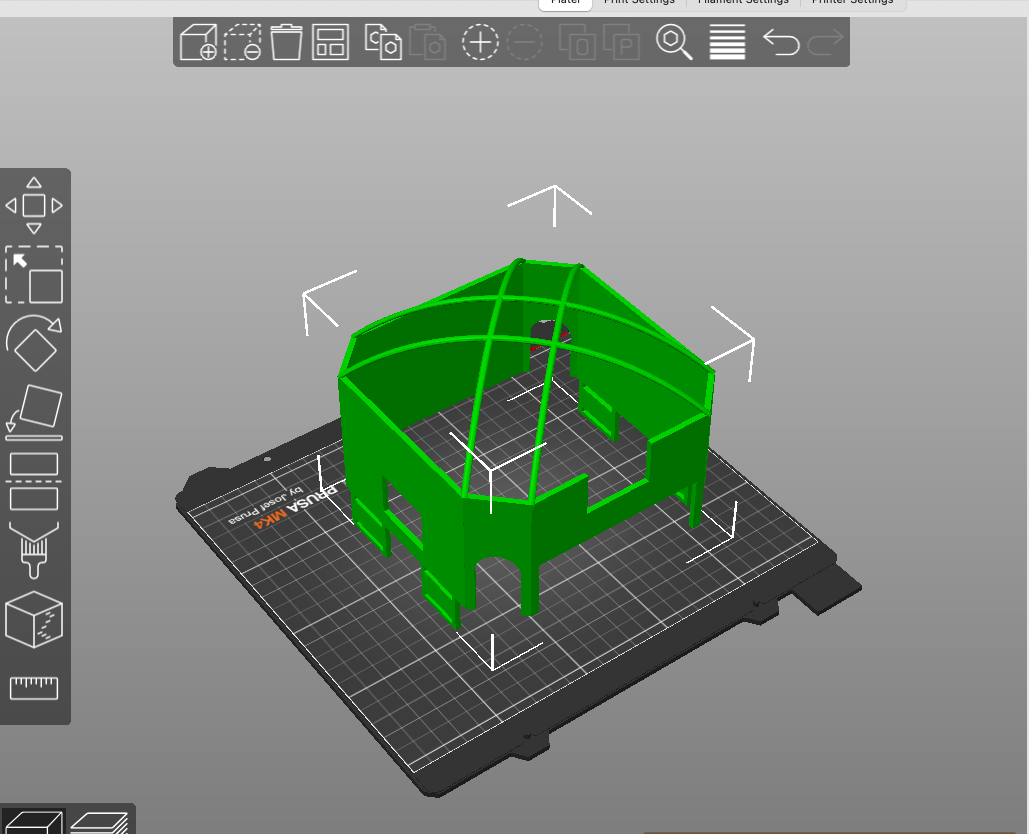
- 3D print the mount board for the Skynode, GPS, and PixHawk Adapter board and put them on the mount. Also 3D print the mount for the LIDAR and Optical Flow sensor.
- The file for the first 3D print will be attached to these instructions and is provided by Auterion. The second can also be supplied by Auterion, but in this project a different optical flow sensor was used and one had to be designed in CAD and 3D printed.
- Once the file is 3D printed, align the Skynode in the center and use M3 or M2.5 screws with a matching nut or locknut on the other end to secure the Skynode to the 3D print. The GPS will go on the extruded triangle section and be screwed in with the supplied screws, which should be M2.5 of a length that will also allow a locknut or regular nut on the other side.
- These screws were scavenged and checked if they fit in the holes and were a length that was sufficient so not much information is known about them.
- Slip the Pixhawk adapter board (which can be split down the center into two between the IO and FMU boards) into the two spots at the end of the 3D printed mount.
- Screw the GPS into the GPS mount, which is the tallest piece on the mount if placed flat down towards the sky.
- Mount the air receiver into the spot next to the Auterion. Do not cover up the fan.
- The 3D print for the LIDAR and optical flow sensor goes on the platform plate with long toleranced holes. These holes can support a wide variety of attachments, so the mount can just be screwed in.
- Mount the 3D print on to the top of the top plate.
- You may need to mark and drill holes through the 3D print if you do not want to use stickers. To drill, tap a starter “hole” or dent into the plastic so the drill has somewhere to catch, and it makes drilling a hole easier and more accurate. Then drill through, making sure these new holes align with those in the top plate, and screw the baseboard down. Depending on the profile or length (which depends on the orientation of how you screwed the Skynode into the plate), you may need a spacer in between the top plate and the mount board.
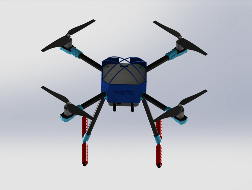
- Mount the propeller arms that came pre-built between the bottom board and the top board.
- There should be slots where pieces of the nylon click into the bottom and top. The placement of the propeller arms is as follows in the figure below. They should be labelled, with the red arrow being the front facing forward.
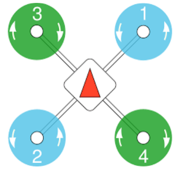 Figure 8.1. Motor location.
- Wire the GPS, LIDAR, Optical flow sensor, and air receiver to the Pixhawk Adapter board.
- The GPS utilizes a JST GH 10pin to a JST GH 8pin cable into J13 on the Pixhawk adapter board.
- The LIDAR utilizes a JST GH 6pin to JST GH 4pin cable into J28 on the Pixhawk adatpter board.
- The air receiver’s SBUS goes into J16, and the telemetry radio goes into J12 on the Pixhawk adapter board.
- The optical flow sensor used utilizes pin outputs from the chip, then is wired into J24 on the Pixhawk adapter which is a JST GH 11pin connector.
- Wire the Auterion to the other components.
- Plug the Auterion in through a JST GH 6 pin cord labelled primary power into J5 and the corresponding 6pin output on the power adapter board provided with the Skynode.
- If you haven’t already, plug the power adapter board into the power distribution board that was installed between the top and bottom carbon fiber plates. Then, the other end can be plugged into a wall source through a female XT60 connector (which should have come with the skynode), or a battery that has an XT60 connector.
- Connect the Auterion to the Pixhawk adapter with the two 40 pin JST GH clasps. One clasp will go from J4 on the Skynode to J11 on the Pixhawk adapter board. The other will go from J6 on the Skynode to J21 on the Pixhawk adapter board.
- Power the drone.
- To power the drone, 2 batteries will be needed. The two batteries used here are Lumenier 5200mAH lipo batteries.
- One battery plugs into the power adapter that leads to both the Skynode and power distribution board.
- The other battery plugs into the air receiver.
- These batteries can be mounted on the battery mounting board utilizing longer velcro or zipties, or they can be duck taped to the landing gear.
- The flight controller was switched between the Auterion SkyNode and the Pixhawk 6X. After flashing both flight controllers and testing them separately, the Pixhawk 6X was used over the SkyNode due to it’s compatibility with more options and ease of use. There are also far more ports available on the Pixhawk 6X without an external extension board being needed.
Results
The drone built flew exceptionally. We were able to plug in different batteries utilizing an XT60 power converter and test their capabilities.
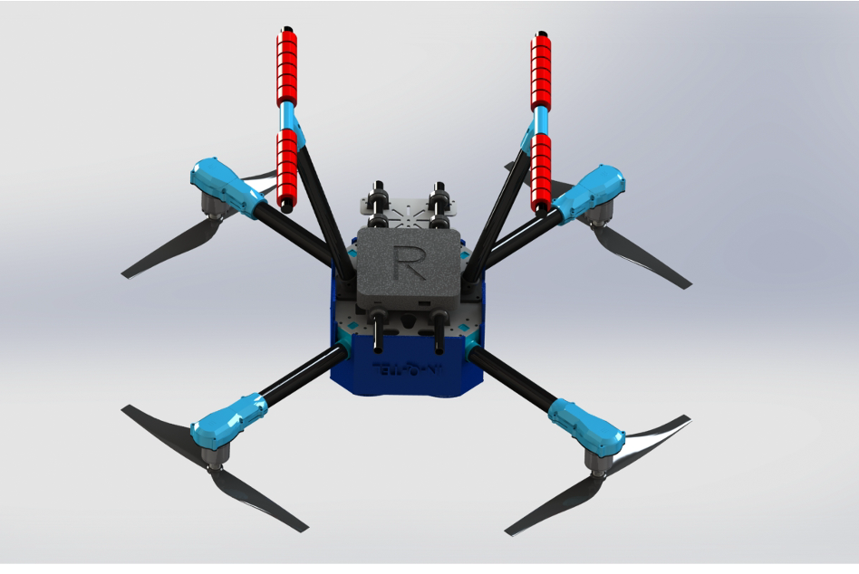
Another part of this project was determining another enhancement that could be made. This chosen enhancement was adding a wireless power unit produced by the company Reach Power. This way the drone could be charged in air without needing to land for power charging. This could be vital for operations that require little down time, or information gathering operations. This could also be paired with drone swarming. The following calculations were done to prove the possibility of this involvement.
- Weight with payload is now 1.8kg, as the Reach Power R104 is 0.45 kg.
- According to the specifications, the motors CAN handle this weight and the propellers can as well. The motors can handle 1.2kg per motor. Code for the calculation can be seen at the bottom of this page, Appendix B.
- To verify the props can support the drone, a lift calculation was done based on the Kutta-Joukowski Theorem.
- For the drone motors, after establishing an understanding of their ratings and how the specification sheets are written, the motors were concluded to be adequate.
- Can support ~3.256kg of weight at 70% Thrust.
- According to the specifications, the motors CAN handle this weight and the propellers can as well. The motors can handle 1.2kg per motor. Code for the calculation can be seen at the bottom of this page, Appendix B.
Appendix
Appendix A: BOM
| Link | Component | Weight (kg) | Power Consumption (A) | Total Weight | Payload Weight | |||
|---|---|---|---|---|---|---|---|---|
| https://holybro.com/products/px4-development-kit-x500-v2 | PX4 V2 (Drone) | 0.61 | 16.66667 | 5000 mAh for 18 min | 1.805545 | 1.195545 | ||
| https://www.getfpv.com/lumenier-5200mah-4s-35c-lipo-battery.html | Luminier 5200 | 0.473 | 5000 mAh | 3.9722 | 2.6302 | |||
| file:///Users/lsamoyan/Downloads/Skynode_Datasheet_v1.3.pdf | Skynode | 0.188 | 5A | 5A/25W max | ||||
| https://store.freeflysystems.com/products/rtk-gps-ground-station | RTK GPS | 0.08 | ||||||
| https://www.bitcraze.io/products/flow-deck-v2/ | Flow Deck V2 | |||||||
| Reach power | R104 | 0.454545 | (RECEIVE 20W) |
Appendix B: Lift Calculation Analysis
import numpy as np
from matplotlib import pyplot
import pandas as pd
import openpyxl

#read datasheet
df = pd.read_excel('') #data removed
print(df)
#variables
omega= 6000 #rpm
R = 127.5/1000 #m
rho = 1.293 #kg/m
s = R*2 #diameter is span?
V_inf = 6 * 0.44704 #m/s, assuming light breeze
m = float( df['Total Weight'][0]) #kg

#lift force
circulation = 2*np.pi*R**2*omega
lift = rho*V_inf*circulation*s
#force of drone weight
weight = m*9.81

def drone_takeoff(lift, weight):
    if lift > weight:
        print('drone will fly, lift surpasses the weight and thus will have an upward acceleration for takeoff')
    else:
        print('drone will NOT fly, lift is either equal to or less than the weight of the drone')
    return

drone_takeoff(lift, weight)